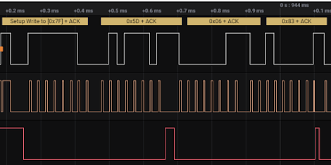
Příspěvky

Yet Another E-Ink Picture Frame

Obrázek
 Yet Another E-Ink Picture Frame In our family we have group on WhatsApp .   To simply share some photos and updates. What bothers me is that our Grandma does not have smartphone, computer even internet and therefore she can not access WhatsApp feed. At first I was thinking about some way how to provide convenient way to share pictures of our children with her. One of the options was to use some old tablet and run WhatsApp there, but this would require some operation to turn the tablet on during the day, maybe restarting it from time to time. It would also be quite data hungry. Then I stumbled over these new fancy 7.3" color E-Ink displays on Pimoroni . And got an idea. Print frame for it attach some single board PC to it and let it ask for update from public web server. For connection I would use LTE WiFi modem.  Important feature is that everything should be simple in way that I can finish this project . So it won't  be yet another unfinished project under my table! Tech St

Building small secondary display

Obrázek
 Building small secondary display And some lesson about modularity Why?      I'm not a big fan of multiple screens, but where it's almost neccessity for me is when Im doing some audio for movie post-production. Main display is used for the audio suite control and on secondary I have video to see what's going on.       What most people do is add secondary display next to the main, but this takes table space that I otherwise need for placing my speakers. And also it's not all that ergonomic, at least for me. So I went with option that I use small display above the main one. How?      I was lucky and once found in e-waste small SONY monitor. That actually fit quite well what I needed. It was old, low resolution and had VGA connector. I painted it (not so well) black to make it somehow prettier. And one of my dump friends manufactured wall holder for it. Time for change      But as the time went I started to look for new solution. With better resolution (not really needed b

Reprogramming "old" Sennheiser Microphone - Part 5 - Writing to Memory and Testing

Obrázek
 Writing and testing  I have table with the values that should be written to into the EEPROM which needed some splitting and padding in order to get it into correct format. Then I added addresses on which data should be written. In this case it should be first 16 channels, that all I need even if there is possible to store up to 32, but the 820-830MHz bandwidth is too narrow for more than 16 channels.  Transformed the addresses and values to array string, odd is address even is value. But I wanted to start with just one value in order to do make any mistake and test if everything is working so I prepared program to write data to first and second bank. Plug the ESP32 on the I2C bus and wait until there is no communication. Push the button, then after removing the ESP32 turn off and on the mic. Which should not be necessary. Set the first channel that I wanted to overwrite and it show this new, correct frequency! But when tuning the receiver to see if everything is working I did not get

Reprogramming "old" Sennheiser Microphone - Part 4 - PLL

Obrázek
 PLL At the beginning when I was looking at the I2C communication I have found out which parts of it talks with PLL, but then I carry on as I did not expect it I will need to understand it better and also since I have very vague idea about what PLL actually is. But now I have to find out in order to compute and load proper data for it into the memory. From the microphone schematics I got the basic idea Red line is quite clearly audio input from the AF microphone part. So its the signal that drives the modulation. Green line is HF output that goes to the HF amplifier stage, thats also quite clear Blue line looks like output from PLL that drives the VCO Yellow is line that goes back from the output to the Prescaler which I have found out is fancy word for frequency divider and then into the PLL  What I thougth PLL is: IC into which you send some f1 and you will get f2 thats locked to the f1 phase. But looking to the datasheet the working frequency of this PLL is actually quite low, much

Reprogramming "old" Sennheiser Microphone - Part 3 - EEPROM

Obrázek
 EEPROM   So, I was able to connect to I2C on the board, see the communication and understand it, little bit. Now the question is, If I'm also able to read the EEPROM without removing it from PCB. Chip is quite small and de/soldering would be painful. Every time you desolder SMT component there is quite high risk that you might remove also the layer of copper which results in destruction of PCB, or in the best case, painful repair.  For the communication the easiest way is to use Arduino board and I2C library, since I have on hand ESP32 I will use this one with Arduino IDE which makes it simple. Thanks to internet there is already a guy who was playing with this particular EEPROM and Arduino, so it makes the effort even easier. Simple Copy-Paste with some modifications to read position 0x10 since I know what is stored there from the I2C communication.  For physical connection I used logic analyzer probes just connected them to the ESP32. Uploaded the program, turn on the mic and w

Reprogramming "old" Sennheiser SKM 3072-U - Part 2 - I2C

Obrázek
 Understanding what is going on I2C In the previous step I hooked up my logic analyzer on the I2C to see how the communication inside the mic actually looks like. Partially because I want to understand better how to reprogram the microphones EEPROM but also because I'm just curious and want to see what is really going on. After powering up the microphone this is the output from I2C. write to 0x3E ack data: 0xE0 0xC8 0xF0 0x00 0x00 0x00 0x00 0x00 0x00 0x00 0x00 0x00  write to 0x3E ack data: 0xE0 0x00 0x00 0x00 0x00 0x00 0x00 0x00 0x00 0x00 0x00 0x00  write to 0x50 ack data: 0x10  read to 0x50 ack data: 0x11 write to 0x51 ack data: 0x1A  read to 0x50 ack data: 0xA9 write to 0x51 ack data: 0xB3  read to 0x50 ack data: 0x1F write to 0x51 ack data: 0xAE  read to 0x50 ack data: 0x03 write to 0x51 ack data: 0xAF  read to 0x50 ack data: 0x20 write to 0x51 ack data: 0xAC  read to 0x50 ack data: 0xFC write to 0x51 ack data: 0xAD  read to 0x50 ack data: 0x5D write to 0x51 ack data: 0xC4  read

Reprogramming "old" Sennheiser SKM 3072-U - Part 1 - Intro

Obrázek
I'm somehow interested in audio production. But not it more my pet hobby, nothing that would generate decent income. This means I usually don't want to spend much of money on the equipment.  Right about now is quite good time to get some old-ish wireless audio equipment for decent price. The reason is that there was change ( info ) in wireless bands and bands that used to be free before are not available for the professional audio anymore. That means that lot of productions are ditching their stuff to buy new one, compatible. But not all the old stuff is useless as some of it can be reprogrammed. There is tight window from 822 to 830 MHz in EU. This window is quite narrow, but at least it should granted all the time for professional audio. Other option is to go below 700Mhz, but then you might get into collision with local TV transmitter. Therefore I settled for the narrow band since I don't plan to use too many transmitters at once and this should work for me well. My movi